Hydronic heating heat loss calculations, mechanical drawings and loop layouts.

ADDRESS

Concord, ON, Canada,

EMAIL

info@looplayouts.com

CALL NOW

+1 647-688-2669

Login
heat loss calculations

Project Info

Project Type

LoopCAD

Clients

Springel Homes

Date

April 5, 2024

Location

Jamaica, VT, USA

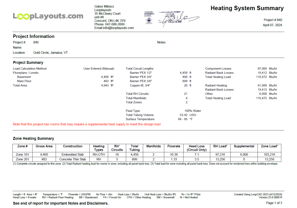
Canadian Hydronics Council Certified and stamped loop layout drawing, heat loss calculation and mechanical design package for building permits. All drawings and calculations needed to draw a residential building permit based on radiant floor heating being the primary source of heat. Does NOT include forced air and ventilation calculations nor duct layout drawings.

  • Residential heat loss calculations with radiant being the primary source of heat by a certified hydronics designer
  • Radiant floor heating loop layout drawings and calculations (loop lengths, flows, temps etc…)
  • Mechanical designs using the hydronic components
  • List of parts with quantities, brands and part numbers (takeoff)
  • Recommended highly skilled installers (if requested)
parts list

Project Info

Project Type

Detailed

Clients

Brad McCollough

Date

June 5, 2023

Location

Aspen, CO, USA

You will receive a list of all major components that the installer will need to supply to implement our design. If you have a preference for boilers, indirect tanks or such we will generate our design and list of components accordingly.

The Challenge

  • To ensure you can purchase all components on the list from your local suppliers
  • To offer alternatives

Project Info

Project Type

CAD Assisted

Clients

Eli Strauss

Date

April 15, 2023

Location

Aspen Colorado

A proper loop layout drawing keeps the installer in mind. LoopCAD can automatically generate elaborate, pretty, utterly useless and nonsensical loop layouts. All our designs are easy to implement, minimize PEX tubing leftovers without compromosing the performance of the system.

While allowing the software to do the calculations we manually draw out every loop to avoid any frustration at the time of install.

The Challenge

  • To minimize loop count without exceeding the maximum allowable loop lenght as per the hydronic building code.
  • To use the least number of manifolds while delivering the required number of heating zones.
  • To use the lowest possible water temperature and yet delivering enough BTU at the design temperature.
Mechanical Room Designs

Project Info

Project Type

Realistic

Clients

Nicolas Marko

Date

March 1, 2021

Location

24 Fifth st.,Los Angeles, USA

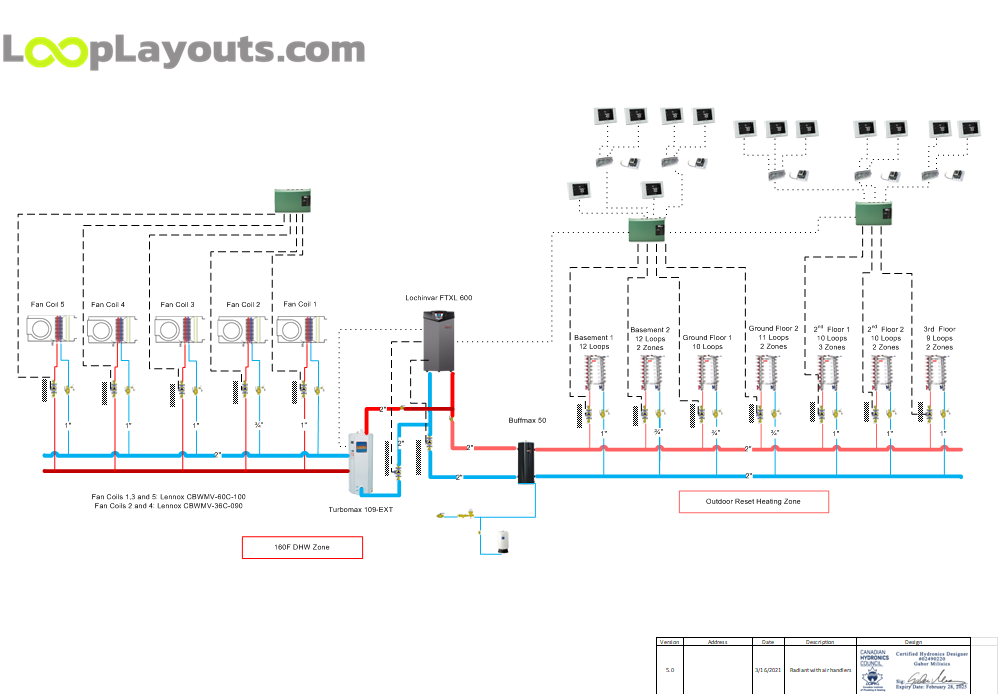
All our designs are easy to visualize and to follow . Every circulator pump is clearly specified, every pipe size, low and high voltage wiring of all components, and temperature settings required is indicated.

The Challenge

  • To show the entire system in an easy to follow format that is suitable for engineers and home owners at the same time.
  • To have all the information on one page that the installer needs without any other drawings or documents.

What you see on paper and on the walls will look the same

Most engineers generate drawings that need a engineering background to fully grasp. Our designs have a realistic view that is easy to visualize without omitting any important details.

Mechanical Room Design Implemented 1
Mechanical Room Design Implemented 2

GET IN TOUCH

Hello, we are a CIPH certified hydronic designer company based in Concord, Ontario, Canada.

info@looplayouts.com

© 2024 Looplayouts.com, All Rights Reserved.